Stressed user reference: Difference between revisions
| Line 97: | Line 97: | ||
* '''Number of paint-jobs''': changes the number of paint-jobs. This is a potentially destructive alteration, so it will only be made effective after clicking away from the selector. | * '''Number of paint-jobs''': changes the number of paint-jobs. This is a potentially destructive alteration, so it will only be made effective after clicking away from the selector. | ||
Finally, some comments on the importing/exporting process. stressed is not intended to be a full fledged 3D editor. Therefore, for large-scale changes to a model, or for creating one from scratch exporting to .OBJ and using an external editor may be the best choice. [http://www.anim8or.com Anim8or], which runs in Windows as well as Linux (under Wine) is well-suited to the kind of operations needed for dealing with Stunts models, but of course the program to be used is at the user's discretion. On the other | Finally, some comments on the importing/exporting process. stressed is not intended to be a full fledged 3D editor. Therefore, for large-scale changes to a model, or for creating one from scratch exporting to .OBJ and using an external editor may be the best choice. [http://www.anim8or.com Anim8or], which runs in Windows as well as Linux (under Wine) is well-suited to the kind of operations needed for dealing with Stunts models, but of course the program to be used is at the user's discretion. On the other hand, for smaller changes and overlaying of details on an existing model the built-in functionalities of stressed are often a more convenient option. Keep in mind that exporting a shape causes loss of 2-sidedness, Z-bias and culling data as well as any paint-jobs other than the one selected at the time of exporting. For that reason, many editors will be unwilling to export models on the late stages of design. | ||
{{Footn|1}} - For the sake of convenience, "polygon" will be taken to stand for graphical primitive in most contexts. | {{Footn|1}} - For the sake of convenience, "polygon" will be taken to stand for graphical primitive in most contexts. | ||
Revision as of 22:51, 15 February 2010
This article aims to be a full-fledged documentation of stressed functions and capabilities. It should be taken as under construction for the foreseeable future. The current version of the article covers revision 53 of stressed.
General program organization
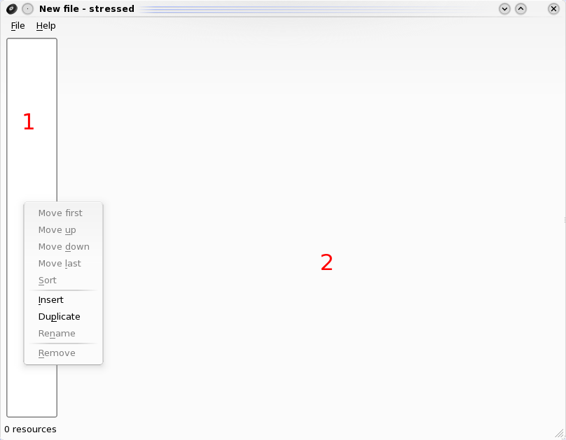
stressed is an editor of resource files of various kinds. A new session of the program looks like this:
To the left of the screen is the resource list (1, shown with the right-click drop-down menu activated). It is empty on the screen shot because a blank resource file is created on opening a new session. The functions on the drop-down menu are available for all sorts of resource files, and are explained below:
- Move first/up/down/last: change the position of a resource on a resource list.
- Sort: sorts resources alphanumerically.
- Insert: inserts resources on the position before the latest-selected resource. The user will be prompted to choose the type of resource to be created. Currently available options are bitmap, shape and text resources.
- Duplicate: duplicates a resource. The user is expected to provide a different 4-letter ID for the duplicate.
- Rename: renames a resource.
- Remove: removes a resource.
Naturally, all drop-down commands other than Sort and Insert require selecting a resource with a left-click.
The right part of the screen is occupied by the interface to the various resource-handling modules, which will be covered in detail shortly.
stressed is capable of opening any proper resource file, but will only parse adequately bitmap, 3D shape and text resources. IDs for known resources of the recognized kinds are stored in an internal database. If a resource is not listed on the database, the user will be prompted to choose either ignoring the resource or attempting to parse as one of the supported types.
Another important observation is with regard to file formats. stressed will open resource files of all kinds irrespective of extension. Compressed files will be uncompressed by the integrated stunpack program. On using the Save command, the originally opened file will be overwritten, with the same extension, irrespective of any file format changes; while with using Save As the user will be expected to provide the correct file extension. It is important to remember that stressed does not compress files on saving; therefore, the unpacked-file extensions should always be used, and after the editing work is done any compressed bitmaps or 3D shape files (.PVS, .P3S) should be moved away from the game folder so that the unpacked files are loaded. Please refer to the Resource file format article for the correct file extension usage.
The bitmap module
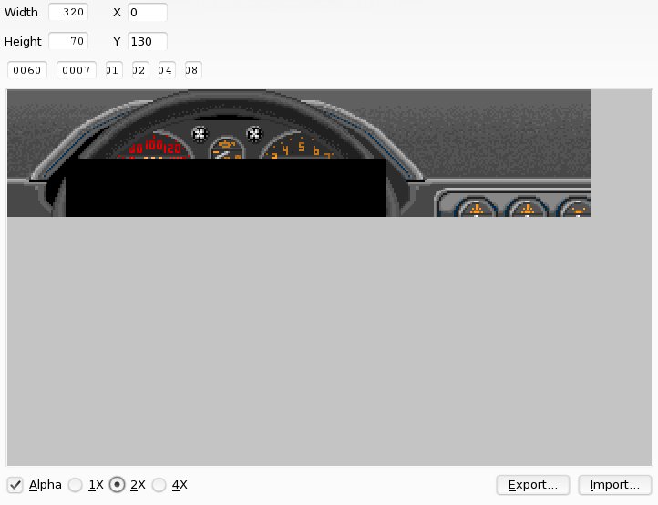
The upper part of the module allows editing of the parameters described on Resource file format#Bitmap Images:
- Width and Height: bitmap dimensions in pixels.
- X and Y: coordinates of the upper-left corner of the bitmap. These are usually screen coordinates (on a 320x200 pixel grid, with the (0,0) point being on the upper-left corner of the screen); for some bitmaps, such as dashboard alpha masks, however, the coordinates may be relative to another bitmap.
- Miscellaneous number fields: unknown1 and unknown2 fields.
The main window displays the currently loaded bitmap. Finally, the commands on the lower part of the screen are:
- Alpha: toggles display of transparency:
- 1X, 2X and 4X: zoom levels of the bitmap display.
- Import and Export: allow importing of and exporting to external image files, making bitmap edition possible with regular image editors. Supported formats are PNG, Windows Bitmap (.bmp) and JPEG - PNG being by far the most convenient option.
A couple extra observations must be made on the importing process. Stunts uses a 256-bit palette, with the FF value being reserved for transparency. stressed can handle RGB images on import, converting them to the correct palette, as well as transparency on image files. Using indexed files actually may make things harder, as you will need to set up the external image editor to use the palette, and transparency data will be lost.
The 3D shape module
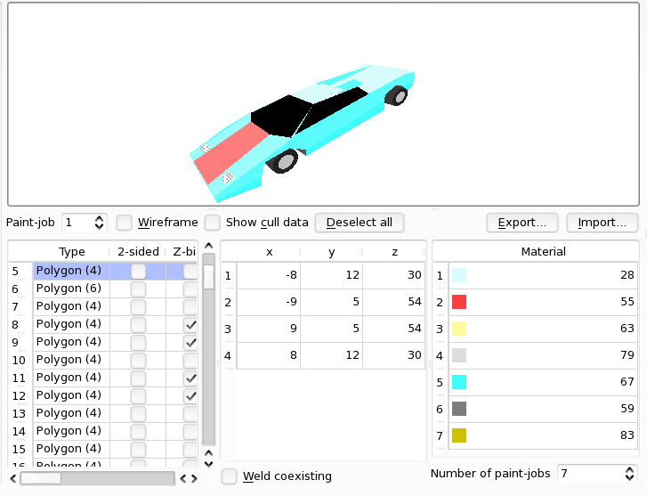
The 3D shape interface is divided into a preview window, which renders the 3D shape in real-time, and a command interface through which individual modifications to polygons [1] and vertexes are made, as well as toggling of global editing and viewing options. First we'll describe the actions possible on the preview window.
- Left click and drag: rotation around X and Y axes of the 3D model.
- Right click and drag: rotation around Z axis of the 3D model.
- Left + right click and drag: vertical displacement of the model
- Middle click and drag: horizontal and perpendicular-to-screen (doubles as zoom in and zoom out) displacement.
- Left click on any polygon: single polygon selection (does not work properly on some flavours of Linux).
- Shift + Left click on polygons: multiple polygon selection.
- Right click on any polygon: single polygon de-selection (from multiple selections) and selection (can be used if left-clicking is buggy on your system).
The visualisation window is occasionally affected by bugs. Sometimes when changing resources the preview may not appear. In that case, just switch back and forth between resources and the preview will load. Also, screen corruption on the window may occur when editing large files (like GAME1/2) for long periods of time. In that case, just save any modifications if desired and reload the file.
Next, we'll describe the three charts occupying most of the command interface. Details about the values and parameters being edited can be found on Resource file format#3D shapes.
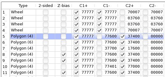
The leftmost panel is the polygon chart. It allows for edition of general polygon properties. In order to do so, a polygon must be selected, either via the preview window or by left-clicking any row on the list. Shift-clicking and Ctrl-clicking allow for multiple selection of polygons (if you experience difficulties with that, try multiple clicks on the row labels while Shift or Ctrl are held). The columns of the chart correspond to:
- (row label): ordering index of the polygon.
- Type: sets the type of graphical primitive - particle, line, polygon with 3 to 10 sides, sphere or wheel.
- 2-sided: sets the polygon as two sided - that is, makes both faces visible. Used for surfaces which have both sides exposed, such as wing plates.
- Z-bias: when turned on, causes the polygon to be displayed over other polygons positioned on the same depth. It is commonly used for details such as door handles and rear lights. A polygon with this flag on must be positioned directly after the base polygon on the polygon list order, otherwise display bugs will arise. (for instance, if the rear panel of a car is at position 46, a set of two rear lights must occupy positions 47 and 48.)
- C1+/- and C2+/-: the sets of culling data which control visibility of polygons from different angles. C1 sets affect the front face of the polygon; C2 sets, the back face. + and - refer to positive and negative viewing directions. The checkboxes are the flags for high vertical angle visibility. The numerical values are the 15-bit sets of culling data (each bit corresponding to 1/15 of a circle) displayed as a 5-digit octal number.
Right-clicking a polygon on the chart opens a pop-up menu with the following options:
- Move first/up/to.../down/last: modify the position of a polygon on the list order. Move to... will prompt the user for a specific position on the list. Note that Move to... will not swap polygons - if polygon 13 is sent to position 84, polygon 14 will go to 13, 15 to 14 and so on up to 84. Move To... was specifically introduced in order to allow easy fixing of order needed for Z-bias flag usage.
- Insert and Duplicate: insert and duplicate polygons.
- Mirror X: creates a duplicate of the polygon with mirrored x coordinates. This command saves work when creating features which will appear on both sides of the car.
- Compute cull data: sets reasonable values for the culling data sets. It is recommended that all polygons are submitted to this treatment for a sane-looking model. Manual fixes might be occasionally needed - in particular if one uses concave or non-planar polygons.
- Remove: removes polygons.
The middle panel is the vertexes table, where individual vertex coordinates can be edited. Double-click any value to edit it. Right-clicking the table make two options available, which affect the polygon as a whole:
- Flip: inverts the ordering of the vertexes. The practical effect is to "flip" the polygon, swapping front and back faces.
- Invert X: mirrors the x coordinates of all vertexes, replacing (and not duplicating) the polygon.
The right panel is the materials table, which allows for changing of the materials (that is, colours as well as occasional extra features) assigned to the polygons on each colour variation/paint-job of the model. Each row of the table corresponds to one of the paint-jobs. Clicking an entry will open a drop-down menu from which the materials can be chosen. Typing the desired texture number with the menu open acts as a shortcut. A preview of the selected materials is displayed on the menu as well; however, many materials have special effects associated with them, and thus it is a good idea to check the list at Shape materials article for reference. Right clicking an entry gives access to the Replace all feature, which allows for a material to be replaced by another in all occurrences within the selected paint-job, thus saving large amounts of time when creating new colour schemes.
There are various important commands located around the panels:
- Paint-job: allows for switching the currently displayed paint-job on the preview window. It is not necessary to switch this option before changing a paint-job on the materials table.
- Wireframe: toggles wireframe display of the model.
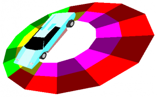
- Show cull data: toggles display of the culling data on the polygon chart C1 and C2 fields. When this option is on and a polygon is selected, the viewing angles will be displayed on a multi-coloured disk. Red or brown circle segments indicate angles from which the polygon is visible; green or yellow segments indicate no visibility. The outer ring represents C1 data; the inner one, C2. When viewed from above, the disk shows + data; from below, -.
- Deselect all: deselects all polygons.
- Import and Export: imports and exports 3D models as Wavefront OBJ files for edition with external 3D editors.
- Weld coexisting: if toggled on, moving a vertex of a polygon will move simultaneously any other vertexes on the same position, making it easier to perform larger-scale modifications to a 3D shape.
- Number of paint-jobs: changes the number of paint-jobs. This is a potentially destructive alteration, so it will only be made effective after clicking away from the selector.
Finally, some comments on the importing/exporting process. stressed is not intended to be a full fledged 3D editor. Therefore, for large-scale changes to a model, or for creating one from scratch exporting to .OBJ and using an external editor may be the best choice. Anim8or, which runs in Windows as well as Linux (under Wine) is well-suited to the kind of operations needed for dealing with Stunts models, but of course the program to be used is at the user's discretion. On the other hand, for smaller changes and overlaying of details on an existing model the built-in functionalities of stressed are often a more convenient option. Keep in mind that exporting a shape causes loss of 2-sidedness, Z-bias and culling data as well as any paint-jobs other than the one selected at the time of exporting. For that reason, many editors will be unwilling to export models on the late stages of design.
1. back - For the sake of convenience, "polygon" will be taken to stand for graphical primitive in most contexts.
The text module
Usage of the text module is straightforward. The interface is equivalent to that of a simple text editor; all that is needed to do is to modify the text and save the file.
